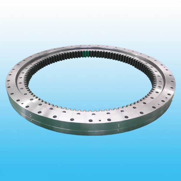
Three Row Roller Bearing Internal Gear


The three row roller slewing bearing has three seat rings,which separate the upper,lower and radial raceways,it made each row of the roller's load capacity can be specified and can bear different loads simultaneously. The capacity load is the largest one compare with the other three models.Due to the large size in axial and radial dimension the solid structure, it is specially suitable for the heavy duty machinery such as wheeled excavator,wheeled crane, ship crane,ladle turrets and the heavy duty mobile crane etc.
Weight/KG: 224-7320
| No. | Inxternal Gear DL mm |
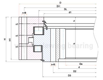
Dimensions | Mounting Dimension | Structural Dimension | Gear Data | Gear circumferential force | Weight kg |
||||||||||||||
| D mm |
d mm |
H mm |
D1 mm |
D2 mm |
n | mm | dm mm |
L mm |
n1 mm |
H1 mm |
h mm |
b mm |
x | m mm |
D e mm |
z | Normalizing Z 104N |
Quenching T 104N |
|||
| 1 | 133.25.500 | 634 | 366 | 148 | 598 | 402 | 24 | 18 | M16 | 32 | 4 | 10 | 32 | 80 | 0.5 | 5 | 337 | 68 | 5.0 | 6.7 | 224 |
| 134.25.500 | 6 | 338.4 | 57 | ||||||||||||||||||
| 2 | 133.25.560 | 694 | 426 | 148 | 658 | 462 | 24 | 18 | M16 | 32 | 4 | 10 | 32 | 80 | 0.5 | 5 | 397 | 80 | 5.0 | 6.7 | 240 |
| 134.25.560 | 6 | 398.4 | 67 | ||||||||||||||||||
| 3 | 133.25.630 | 764 | 496 | 148 | 728 | 532 | 28 | 18 | M16 | 32 | 4 | 10 | 32 | 80 | 0.5 | 6 | 458.4 | 77 | 6.0 | 8 | 270 |
| 134.25.630 | 8 | 459.2 | 58 | ||||||||||||||||||
| 4 | 133.25.710 | 844 | 576 | 148 | 808 | 612 | 28 | 18 | M16 | 32 | 4 | 10 | 32 | 80 | 0.5 | 6 | 536.4 | 90 | 6.0 | 8 | 300 |
| 134.25.710 | 8 | 539.2 | 68 | ||||||||||||||||||
| 5 | 133.32.800 | 964 | 636 | 182 | 920 | 680 | 36 | 22 | M20 | 40 | 4 | 10 | 40 | 120 | 0.5 | 8 | 595.2 | 75 | 12.1 | 16.7 | 500 |
| 134.32.800 | 10 | 594 | 60 | ||||||||||||||||||
| 6 | 133.32.900 | 1064 | 736 | 182 | 1020 | 780 | 36 | 22 | M20 | 40 | 4 | 10 | 40 | 120 | 0.5 | 8 | 691.2 | 87 | 12.1 | 16.7 | 600 |
| 134.32.900 | 10 | 694 | 70 | ||||||||||||||||||
| 7 | 133.32.1000 | 1164 | 836 | 182 | 1120 | 880 | 40 | 22 | M20 | 40 | 5 | 10 | 40 | 120 | 0.5 | 10 | 784 | 79 | 15.1 | 20.9 | 680 |
| 134.32.1000 | 12 | 784.8 | 66 | ||||||||||||||||||
| 8 | 133.32.1120 | 1284 | 956 | 182 | 1240 | 1000 | 40 | 22 | M20 | 40 | 5 | 10 | 40 | 120 | 0.5 | 10 | 904 | 91 | 15.1 | 20.9 | 820 |
| 134.32.1120 | 12 | 904.8 | 76 | ||||||||||||||||||
| 9 | 133.40.1250 | 1445 | 1055 | 220 | 1393 | 1107 | 45 | 26 | M24 | 48 | 5 | 10 | 50 | 150 | 0.5 | 12 | 988.8 | 83 | 22.9 | 31.4 | 1200 |
| 134.40.1250 | 14 | 985.6 | 71 | ||||||||||||||||||
| 10 | 133.40.1400 | 1595 | 1205 | 220 | 1543 | 1257 | 45 | 26 | M24 | 48 | 5 | 10 | 50 | 150 | 0.5 | 12 | 1144.8 | 96 | 22.9 | 31.4 | 1300 |
| 134.40.1400 | 14 | 1139.6 | 82 | ||||||||||||||||||
| 11 | 133.40.1600 | 1795 | 1405 | 220 | 1743 | 1457 | 48 | 26 | M24 | 48 | 6 | 10 | 50 | 150 | 0.5 | 14 | 1335.6 | 96 | 26.3 | 36.6 | 1520 |
| 134.40.1600 | 16 | 1334.4 | 84 | ||||||||||||||||||
| 12 | 133.40.1800 | 1995 | 1605 | 220 | 1943 | 1657 | 48 | 26 | M24 | 48 | 6 | 10 | 50 | 150 | 0.5 | 14 | 1531.6 | 110 | 26.3 | 36.6 | 1750 |
| 134.40.1800 | 16 | 1526.4 | 96 | ||||||||||||||||||
| 13 | 133.45.2000 | 2221 | 1779 | 231 | 2155 | 1845 | 60 | 33 | M30 | 60 | 6 | 12 | 54 | 160 | 0.5 | 16 | 1702.4 | 107 | 32.2 | 44.5 | 2400 |
| 134.45.2000 | 18 | 1699.2 | 95 | ||||||||||||||||||
| 14 | 133.45.2240 | 2461 | 2019 | 231 | 2395 | 2085 | 60 | 33 | M30 | 60 | 6 | 12 | 54 | 160 | 0.5 | 16 | 1926.4 | 121 | 32.2 | 44.5 | 2700 |
| 134.45.2240 | 18 | 1933.2 | 108 | ||||||||||||||||||
| 15 | 133.45.2500 | 2721 | 2279 | 231 | 2655 | 2345 | 72 | 33 | M30 | 60 | 8 | 12 | 54 | 160 | 0.5 | 18 | 2185.2 | 122 | 36.2 | 50.1 | 3000 |
| 134.45.2500 | 20 | 2188 | 110 | ||||||||||||||||||
| 16 | 133.45.2800 | 3021 | 2579 | 231 | 2955 | 2645 | 72 | 33 | M30 | 60 | 8 | 12 | 54 | 160 | 0.5 | 18 | 2491.2 | 139 | 36.2 | 50.1 | 3400 |
| 134.45.2800 | 20 | 2488 | 125 | ||||||||||||||||||
| 17 | 133.50.3150 | 3432 | 2868 | 270 | 3342 | 2958 | 72 | 45 | M42 | 84 | 8 | 12 | 65 | 180 | 0.5 | 20 | 2768 | 139 | 45.2 | 62.6 | 5000 |
| 134.50.3150 | 22 | 2758.8 | 126 | ||||||||||||||||||
| 18 | 133.50.3550 | 3832 | 3268 | 270 | 3742 | 3358 | 72 | 45 | M42 | 84 | 8 | 258 | 65 | 180 | 0.5 | 20 | 3168 | 159 | 45.2 | 62.6 | 5680 |
| 134.50.3500 | 22 | 3154.8 | 144 | 49.8 | 68.9 | ||||||||||||||||
| 19 | 133.50.4000 | 4282 | 3718 | 270 | 4192 | 3808 | 80 | 45 | M42 | 84 | 8 | 258 | 65 | 180 | 0.5 | 22 | 3116.8 | 165 | 49.8 | 68.9 | 6470 |
| 134.50.4000 | 25 | 3610 | 145 | 56.5 | 78.3 | ||||||||||||||||
| 20 | 133.50.4500 | 4782 | 4218 | 270 | 4692 | 4308 | 80 | 45 | M42 | 84 | 8 | 258 | 65 | 180 | 0.5 | 22 | 4122.8 | 188 | 49.8 | 68.9 | 7320 |
| 134.50.4500 | 25 | 4110 | 165 | 56.5 | 78.3 | ||||||||||||||||
Note:
1. N1 is the numbers of lubricating holes. Oil cup M10×1JB/T7940.1~JB/T7940.
2. The Oil nipple's location can be change according to the user's application.
2. n-φ can change to tapped hole, the diameter of tapped hole is M, and depth is 2M.
3. The tangential tooth force in the form is the max tooth force; the nominal tangential tooth force is 1/2 of the max one.
4. "K" is addendum reduction coefficient.

