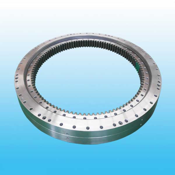
Double Row Ball Bearing Internal Gear


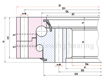
Double row ball slewing bearing has three seat ring, the steel ball and the spacing block can be directly arrange into the upper and lower races, two rows of upper and lower steel balls with differently diameter are fitted according to the stress condition.
This kind of open assemly is very convenient, for the upper and lower bear raceway arc angles is 90, which can bear large axial forces and tilting moment. When the radial force is greater than 0.1 times the axial force need to be specially designed the raceway.
Double row different ball slewing bearing's axial and radial size are relatively large and solid in structure, so it is specially fpr the medium diameter tower cranes,truck mounted cranes etc.loading and unloading machinery.
Weight/KG: 100-4700
| No | Internal Gear DL mm |
Dimensions | Mounting Dimension | Structural Dimension | Gear Data | Gear circumferential force | Weight kg |
||||||||||||
| D mm |
d mm |
H mm |
D1 mm |
D2 mm |
n | mm | n1 mm |
H1 mm |
h mm |
b mm |
x | m mm |
D e mm |
z | Normalizing Z 104N |
Quenching T 104N |
|||
| 1 | 023.25.500 | 616 | 384 | 106 | 580 | 420 | 20 | 18 | 4 | 96 | 26 | 60 | 0.5 | 5 | 257 | 72 | 3.7 | 5.2 | 100 |
| 024.25.500 | 6 | 350.4 | 59 | 4.5 | 6.2 | ||||||||||||||
| 2 | 023.25.560 | 676 | 444 | 106 | 640 | 480 | 20 | 18 | 4 | 96 | 26 | 60 | 0.5 | 5 | 417 | 84 | 3.7 | 5.2 | 115 |
| 024.25.560 | 6 | 410.4 | 69 | 4.5 | 6.2 | ||||||||||||||
| 3 | 023.25.630 | 746 | 514 | 106 | 710 | 550 | 24 | 18 | 4 | 96 | 26 | 60 | 0.5 | 6 | 482.4 | 81 | 4.5 | 6.2 | 130 |
| 024.25.630 | 8 | 475.2 | 60 | 6 | 8.3 | ||||||||||||||
| 4 | 023.25.710 | 826 | 594 | 106 | 790 | 630 | 24 | 18 | 4 | 96 | 26 | 60 | 0.5 | 6 | 560.4 | 94 | 4.5 | 6.2 | 140 |
| 024.25.710 | 8 | 555.2 | 70 | 6 | 8.3 | ||||||||||||||
| 5 | 023.30.800 | 942 | 658 | 124 | 898 | 702 | 30 | 22 | 6 | 114 | 29 | 80 | 0.5 | 8 | 619.2 | 78 | 8 | 11.1 | 200 |
| 024.30.800 | 10 | 614 | 62 | 10 | 14 | ||||||||||||||
| 6 | 023.30.900 | 1042 | 758 | 124 | 998 | 802 | 30 | 22 | 6 | 114 | 29 | 80 | 0.5 | 8 | 715.2 | 90 | 8 | 11.1 | 250 |
| 024.30.900 | 10 | 714 | 72 | 10 | 14 | ||||||||||||||
| 7 | 023.30.1000 | 1142 | 858 | 124 | 1098 | 902 | 36 | 22 | 6 | 114 | 29 | 80 | 0.5 | 10 | 814 | 82 | 10 | 14 | 300 |
| 024.30.1000 | 12 | 796.8 | 67 | 12 | 16.7 | ||||||||||||||
| 8 | 023.30.1120 | 1262 | 978 | 124 | 1218 | 1022 | 36 | 22 | 6 | 114 | 29 | 80 | 0.5 | 10 | 924 | 93 | 10 | 14 | 340 |
| 024.30.1120 | 12 | 916.8 | 77 | 12 | 16.7 | ||||||||||||||
| 9 | 023.40.1250 | 1426 | 1074 | 160 | 1374 | 1126 | 40 | 26 | 5 | 150 | 39 | 90 | 0.5 | 12 | 1012.8 | 85 | 13.5 | 18.8 | 580 |
| 024.40.1250 | 14 | 1013.6 | 73 | 15.8 | 21.9 | ||||||||||||||
| 10 | 023.40.1400 | 1576 | 1224 | 160 | 1524 | 1272 | 40 | 26 | 5 | 150 | 39 | 90 | 0.5 | 12 | 1156.8 | 97 | 13.5 | 18.8 | 650 |
| 024.40.1400 | 14 | 1153.6 | 83 | 15.8 | 21.9 | ||||||||||||||
| 11 | 023.40.1600 | 1776 | 1424 | 160 | 1724 | 1476 | 45 | 26 | 5 | 150 | 39 | 90 | 0.5 | 14 | 1349.6 | 97 | 15.8 | 21.9 | 750 |
| 024.40.1600 | 16 | 1350.4 | 85 | 18.1 | 25 | ||||||||||||||
| 12 | 023.40.1800 | 1976 | 1624 | 160 | 1924 | 1676 | 45 | 26 | 5 | 150 | 39 | 90 | 0.5 | 14 | 1545.6 | 111 | 15.8 | 21.9 | 820 |
| 024.40.1800 | 16 | 1542.4 | 97 | 18.1 | 25 | ||||||||||||||
| 13 | 023.50.2000 | 2215 | 1785 | 190 | 2149 | 1851 | 48 | 33 | 8 | 178 | 47 | 120 | 0.5 | 16 | 1702.4 | 107 | 24.1 | 33.3 | 1150 |
| 024.50.2000 | 18 | 1699.2 | 95 | 27.1 | 37.5 | ||||||||||||||
| 14 | 023.50.2240 | 2455 | 2025 | 190 | 2389 | 2091 | 48 | 33 | 8 | 178 | 47 | 120 | 0.5 | 16 | 1942.4 | 122 | 24.1 | 33.3 | 1500 |
| 024.50.2240 | 18 | 1933.2 | 108 | 27.1 | 37.5 | ||||||||||||||
| 15 | 023.50.2500 | 2715 | 2285 | 190 | 2649 | 2351 | 56 | 33 | 8 | 178 | 47 | 120 | 0.5 | 18 | 2203.2 | 123 | 27.1 | 37.5 | 1700 |
| 024.50.2500 | 20 | 2188 | 110 | 30.1 | 41.8 | ||||||||||||||
| 16 | 023.50.2800 | 3015 | 2585 | 190 | 2949 | 2651 | 56 | 33 | 8 | 178 | 47 | 120 | 0.5 | 18 | 2491.2 | 139 | 27.1 | 37.5 | 1900 |
| 024.50.2800 | 20 | 2488 | 125 | 30.1 | 41.8 | ||||||||||||||
| 17 | 023.60.3150 | 3428 | 2872 | 226 | 3338 | 2962 | 56 | 45 | 8 | 214 | 56 | 150 | 0.5 | 20 | 2768 | 139 | 37.7 | 52.2 | 3300 |
| 024.60.3150 | 22 | 2758.8 | 126 | 41.5 | 57.4 | ||||||||||||||
| 18 | 023.60.3550 | 3828 | 3272 | 226 | 3738 | 3362 | 56 | 45 | 8 | 214 | 56 | 150 | 0.5 | 20 | 3168 | 159 | 37.7 | 52.2 | 3700 |
| 024.60.3550 | 22 | 3176.8 | 145 | 41.5 | 57.4 | ||||||||||||||
| 19 | 023.60.4000 | 4278 | 3722 | 226 | 4188 | 3812 | 60 | 45 | 10 | 214 | 56 | 150 | 0.5 | 22 | 3616.8 | 165 | 41.5 | 57.4 | 4200 |
| 024.60.4000 | 25 | 3610 | 145 | 47.1 | 65.2 | ||||||||||||||
| 20 | 023.60.4500 | 4778 | 4222 | 226 | 4688 | 4312 | 60 | 45 | 10 | 214 | 56 | 150 | 0.5 | 22 | 4122.8 | 188 | 41.5 | 57.4 | 4700 |
| 024.60.4500 | 25 | 4110 | 165 | 47.1 | 65.2 | ||||||||||||||
Note:
1. N1 is the numbers of lubricating holes. Oil cup M10×1JB/T7940.1~JB/T7940.
2. The Oil nipple's location can be change according to the user's application.
3. n-φ can change to tapped hole, the diameter of tapped hole is M, and depth is 2M.
4. The tangential tooth force in the form is the max tooth force; the nominal tangential tooth force is 1/2 of the max one.
5. "K" is addendum reduction coefficient.

